Notice
Transition is currently unavailable. Maintenance in progress.


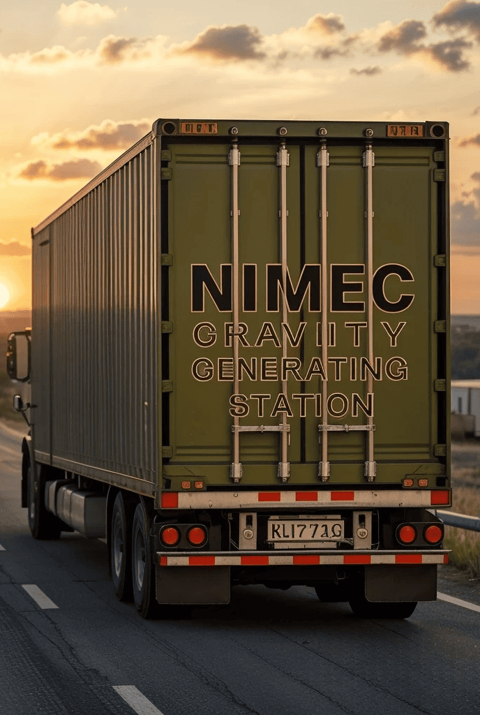
Closed-Cycle Hydro Modules Powered by Magnetic Drive.
NIMEC proudly presents the world’s first modular power station as
Container-Based Power technology! This innovative system is a fully
autonomous electricity generation station, assembled from six High Cube 40-foot
containers. The station is delivered in a Plug & Play format — all you need is
a levelled site. Our specialists will handle delivery, installation, and
commissioning of the equipment on a turnkey basis.
We use a Pelton turbine because it is one of the most efficient impulse-type
hydraulic turbines, perfectly suited for high-head liquid applications. It
transforms the kinetic energy of a powerful jet into rotational mechanical
energy with minimal losses. The high-pressure jet is directed through a nozzle
and strikes the specially designed buckets arranged around the turbine wheel.
Thanks to the unique shape of the buckets, the liquid is redirected by nearly
180°, enabling maximum energy transfer and producing a strong torque.
In our station, we employ a heavy liquid — an 70% solution of zinc iodide
(ZnI₂, CAS 10139-47-6) — chosen for its high density. This innovative solution
allows for the most effective utilization of the Earth’s gravitational field,
converting it efficiently into mechanical shaft rotation. By feeding the heavy
liquid onto the Pelton turbine buckets from above, we have achieved outstanding
system efficiency. This liquid is completely environmentally safe, circulating
within a closed and sealed loop, ensuring sterile operation and significantly
extending the service life of the equipment. Moreover, using a heavy liquid
significantly reduces the volume needed compared to traditional water-based
solutions, simplifying the system and lowering operational costs.
The reduced volume of heavy liquid and the use of modern materials allowed us
to employ high-speed hydro- and pneumatic cylinders. These cylinders efficiently
receive energy from compressed air and transfer it to the heavy liquid,
maintaining continuous circulation. Powerful compressors compress the air,
which also circulates within a closed-loop system, maintaining constant air
quality essential for long-term reliable compressor operation. The sealed
circulation of both liquid and air ensures the station’s autonomy and stable
operation, regardless of environmental conditions.
We utilize permanent magnet generators, which offer a high efficiency rate by
eliminating the need for external excitation — the magnetic field is created by
the magnets themselves. This reduces energy losses, simplifies the design,
minimizes heating and mechanical wear. As a result, our generators operate more
quietly, reliably, and efficiently, and have a longer lifespan compared to
traditional electric machines. By using permanent magnet generators, we can
transform almost 100% of mechanical energy into electrical energy with minimal
losses.
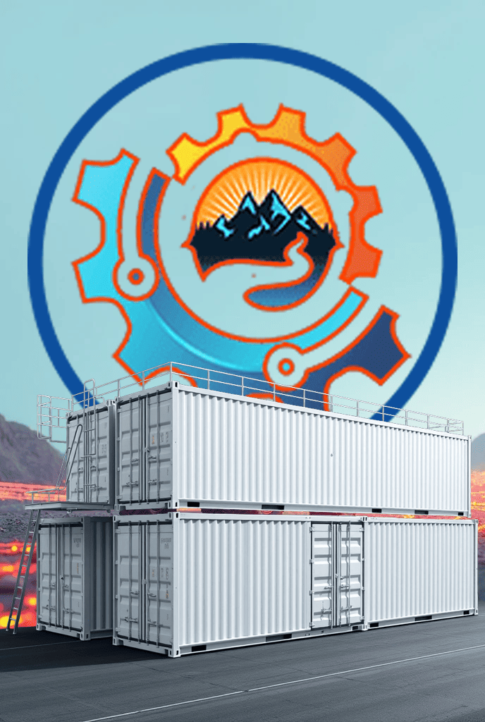
The module consists of six containers arranged in two horizontal rows. Vertical
support columns are installed between and at the ends of the containers,
forming a structural frame that provides overall rigidity. Attached to the
columns are three levels of service platforms: the first positioned 200 mm above
ground level, the second aligned with the top of the lower container row, and
the third aligned with the top of the upper row. These platforms provide access
for maintenance personnel.
The containers are equipped with side and end doors to ensure convenient access.
All blocks are fitted with fire suppression systems, remote control units, and
emergency stop functions. The system can be started or stopped either locally
or remotely.
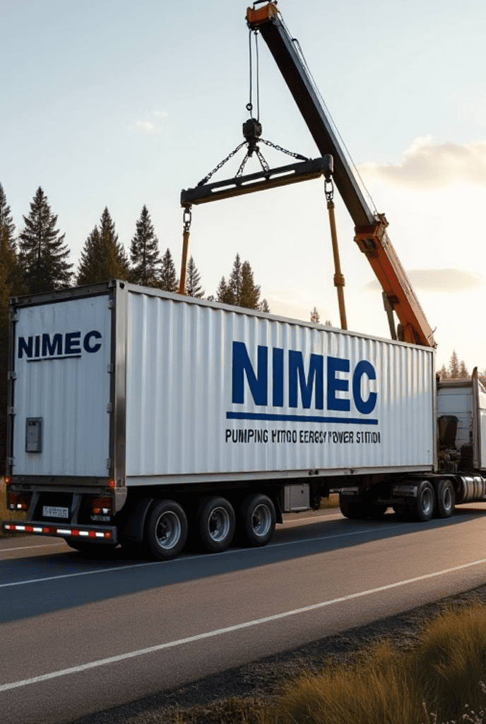
The system is delivered as a set of eight 40-foot High Cube containers. Two of
these containers are used to house components and assemblies that could not be
accommodated within the six primary containers. After installation and
commissioning of the module, these auxiliary containers may be removed from the
site or repurposed as a separate technical unit according to customer
requirements.
Between the two containers of the lower row is a central container housing two
sets of 180 cylinders each. The cylinders are used to process a heavy liquid
(a 70% zinc iodide solution), which flows into them without pressure after
exiting the Pelton turbine and is then directed to the impulse node accumulator,
rated for a maximum pressure of 350 bar. Two linear pipelines extend from the
accumulator to the Pelton turbine’s impulse system. The container also houses
pipelines for supplying inert gas (nitrogen) at 450 bar and discharging it at
12 bar, along with local lines for feeding and draining liquid from the
cylinder groups.
On one side of the central container in the lower row is a container for inert gas
storage and supply. It includes two high-pressure compressors, each driven by a NIMEC
magnetic motor of appropriate capacity; a gas receiver rated to 15 bar; and twelve
50-litre cylinders pressurised to 300 bar for inert gas storage. Each compressor is
equipped with a controller, safety assemblies, and a gas conditioning unit. The
cylinders serve to initiate the circulation system and supply the fire suppression
unit. They feature external refueling ports and safety blocks, allowing gas refilling
without entering the container.
On the opposite side of the central container is a container housing a local
control room with an external communication unit, storage cabinets for tools,
consumables, and documentation. This container also contains a local magnetic
generator unit that powers the compressors, system controllers, cooling and
ventilation units, fire suppression system, and module lighting.
At the centre of the upper level, above the cylinder group container, is a
container with a Pelton bucket turbine, generators based on permanent magnets
and mounted on both sides of the turbine shaft, with a total output of 5, 8 or
10 MW. The generators are equipped with control units and emergency shutdown
systems. The turbine is enclosed in a casing, to which the nozzle and deflection
inserts are attached via flanged connections. The nozzle has a conical shape
and is positioned to deliver the heavy liquid jet from above, targeting the
centre of the bucket blade edge at an optimal 90° angle. A pneumatically operated
valve is installed in front of the nozzle, connected to a tee that merges two
fluid supply lines from the impulse accumulator. The deflection inserts return
the jet into the buckets, allowing recovery of residual kinetic energy.
On one side of the central container in the upper row, above the control room,
is a container housing inverters, transformers, and connection switchgear.
The inverters stabilise and synchronise frequency and voltage for the
transformers. The transformers produce output voltage of either 6.3 kV or 11 kV
at 50 or 60 Hz. The electrical interface is achieved through three switchgear
units: one common and one for each transformer.
On the opposite side, above the compressor container, is a container with two
supercapacitor banks for energy storage and continuous delivery. This container
also includes a high-speed EV charging module with a plug-in station.